This article discusses the following:
The subroutine linkage convention describes the machine state at subroutine entry and exit. When followed, this scheme allows routines compiled separately in the same or different languages to be linked and executed when called.
The linkage convention allows for parameter passing and return values to be in floating-point registers (FPRs), general-purpose registers (GPRs), or both.
For AIX Version 4.3, the following discussion applies to both 32-bit mode and 64-bit mode with the following notes:
The PowerPC 32-bit architecture has 32 GPRs and 32 FPRs. Each GPR is 32 bits wide, and each FPR is 64 bits wide. There are also special registers for branching, exception handling, and other purposes. The General-Purpose Register Convention table shows how GPRs are used.
| General-Purpose Register Conventions | ||
| Register | Status | Use |
| GPR0 | volatile | In function prologs. |
| GPR1 | dedicated | Stack pointer. |
| GPR2 | dedicated | Table of Contents (TOC) pointer. |
| GPR3 | volatile | First word of a function's argument list; first word of a scalar function return. |
| GPR4 | volatile | Second word of a function's argument list; second word of a scalar function return. |
| GPR5 | volatile | Third word of a function's argument list. |
| GPR6 | volatile | Fourth word of a function's argument list. |
| GPR7 | volatile | Fifth word of a function's argument list. |
| GPR8 | volatile | Sixth word of a function's argument list. |
| GPR9 | volatile | Seventh word of a function's argument list. |
| GPR10 | volatile | Eighth word of a function's argument list. |
| GPR11 | volatile | In calls by pointer and as an environment pointer for languages that require it (for example, PASCAL). |
| GPR12 | volatile | For special exception handling required by certain languages and in glink code. |
| GPR13:GPR31 | nonvolatile | These registers must be preserved across a function call. |
The preferred method of using GPRs is to use the volatile registers first. Next, use the nonvolatile registers in descending order, starting with GPR31 and proceeding down to GPR13. GPR1 and GPR2 must be dedicated as stack and Table of Contents (TOC) area pointers, respectively. GPR1 and GPR2 must appear to be saved across a call, and must have the same values at return as when the call was made.
Volatile registers are scratch registers presumed to be destroyed across a call and are, therefore, not saved by the callee. Volatile registers are also used for specific purposes as shown in the previous table. Nonvolatile and dedicated registers are required to be saved and restored if altered and, thus, are guaranteed to retain their values across a function call.
The Floating-Point Register Conventions table shows how the FPRs are used.
| Floating-Point Register Conventions | ||
| Register | Status | Use |
| FPR0 | volatile | As a scratch register. |
| FPR1 | volatile | First floating-point parameter; first 8 bytes of a floating-point scalar return. |
| FPR2 | volatile | Second floating-point parameter; second 8 bytes of a floating-point scalar return. |
| FPR3 | volatile | Third floating-point parameter; third 8 bytes of a floating-point scalar return. |
| FPR4 | volatile | Fourth floating-point parameter; fourth 8 bytes of a floating-point scalar return. |
| FPR5 | volatile | Fifth floating-point parameter. |
| FPR6 | volatile | Sixth floating-point parameter. |
| FPR7 | volatile | Seventh floating-point parameter. |
| FPR8 | volatile | Eighth floating-point parameter. |
| FPR9 | volatile | Ninth floating-point parameter. |
| FPR10 | volatile | Tenth floating-point parameter. |
| FPR11 | volatile | Eleventh floating-point parameter. |
| FPR12 | volatile | Twelfth floating-point parameter. |
| FPR13 | volatile | Thirteenth floating-point parameter. |
| FPR14:FPR31 | nonvolatile | If modified, must be preserved across a call. |
The preferred method of using FPRs is to use the volatile registers first. Next, the nonvolatile registers are used in descending order, starting with FPR31 and proceeding down to FPR14.
Only scalars are returned in multiple registers. The number of registers required depends on the size and type of the scalar. For floating-point values, the following results occur:
The Special-Purpose Register Conventions table shows the PowerPC special purpose registers (SPRs). These are the only SPRs for which there is a register convention.
| Special-Purpose Register Conventions | ||
| Register or Register Field | Status | Use |
| LR | volatile | Used as a branch target address or holds a return address. |
| CTR | volatile | Used for loop count decrement and branching. |
| XER | volatile | Fixed-point exception register. |
| FPSCR | volatile | Floating-point exception register. |
| CR0, CR1 | volatile | Condition-register bits. |
| CR2, CR3, CR4 | nonvolatile | Condition-register bits. |
| CR5, CR6, CR7 | volatile | Condition-register bits. |
Routines that alter CR2, CR3, and CR4 must save and restore at least these fields of the CR. Use of other CR fields does not require saving or restoring.
The stack format convention is designed to enhance the efficiency of the following:
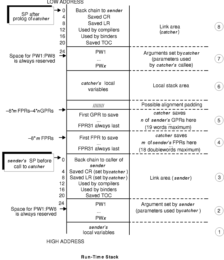
The Run-Time Stack figure illustrates the run-time stack. It shows the stack after the sender function calls the catcher function, but before the catcher function calls another function. This figure is based on the assumption that the catcher function will call another function. Therefore, the catcher function requires another link area (as described in the stack layout). PWn refers to the nth word of parameters that are passed.
Only one register, referred to as the stack pointer (SP), is used for addressing the stack, and GPR1 is the dedicated stack pointer register. It grows from numerically higher storage addresses to numerically lower addresses.
The Run-Time Stack figure illustrates what happens when the sender function calls the catcher function, and how the catcher function requires a stack frame of its own. When a function makes no calls and requires no local storage of its own, no stack frame is required and the SP is not altered.
Notes:
- To reduce confusion, data being passed from the sender function (the caller) is referred to as arguments, and the same data being received by the catcher function (the callee) is referred to as parameters. The output argument area of sender is the same as the input parameter area of catcher.
- The address value in the stack pointer must be quadword-aligned. (The address value must be a multiple of 16.)
For convenience, the stack layout has been divided into eight areas numbered 1 to 8, starting from the bottom of the diagram (high address) to the top of the diagram (low address). The sender's stack pointer is pointing to the top of area 3 when the call to the catcher function is made, which is also the same SP value that is used by the catcher function on entry to its prolog. The following is a description of the stack areas, starting from the bottom of the diagram (area 1) and moving up to the top (area 8):
Area 1 is the local variable area for the sender function, contains all local variables and temporary space required by this function.
Area 2 is the output argument area for the sender function. This area is at least eight words in size and must be doubleword-aligned. The first eight words are not used by the caller (the sender function) because their corresponding values are placed directly in the argument registers (GPR3:GPR10). The storage is reserved so that if the callee (the catcher function) takes the address of any of its parameters, the values passed in GPR3:GPR10 can be stored in their address locations (PW1:PW8, respectively). If the sender function is passing more than eight arguments to the catcher function, then it must reserve space for the excess parameters. The excess parameters must be stored as register images beyond the eight reserved words starting at offset 56 from the sender function's SP value.
Note: This area may also be used by language processors and is volatile across calls to other functions.
Area 3 is the link area for the sender function. This area consists of six words and is at offset 0 from the sender function's SP at the time the call to the catcher function is made. Certain fields in this area are used by the catcher function as part of its prolog code, those fields are marked in the Run-Time Stack figure and are explained below.
The first word is the back chain, the location where the sender function saved its caller's SP value prior to modifying the SP. The second word (at offset 4) is where the catcher function can save the CR if it modifies any of the nonvolatile CR fields. The third word (offset 8) is where the catcher function can save the LR if the catcher function makes any calls.
The fourth word is reserved for compilers, and the fifth word is used by binder-generated instructions. The last word in the link area (offset 20) is where the TOC area register (see "Understanding and Programming the TOC" for description) is saved by the global linkage (glink) interface routine. This occurs when an out-of-module call is performed, such as when a shared library function is called.
Area 4 is the floating-point register save area for the callee (the catcher function) and is doubleword-aligned. It represents the space needed to save all the nonvolatile FPRs used by the called program (the catcher function). The FPRs are saved immediately above the link area (at a lower address) at a negative displacement from the sender function's SP. The size of this area varies from zero to a maximum of 144 bytes, depending on the number of FPRs being saved (maximum number is 18 FPRs * 8 bytes each).
Area 5 is the general-purpose register save area for the catcher function and is at least word-aligned. It represents the space needed by the called program (the catcher function) to save all the nonvolatile GPRs. The GPRs are saved immediately above the FPR save area (at a lower address) at a negative displacement from the sender function's SP. The size of this area varies from zero to a maximum of 76 bytes, depending on the number of GPRs being saved (maximum number is 19 GPRs * 4 bytes each).
Notes:The system-defined stack floor includes the maximum possible save area. The formula for the size of the save area is:
- A stackless leaf procedure makes no calls and requires no local variable area, but it may use nonvolatile GPRs and FPRs.
- The save area consists of the FPR save area (4) and the GPR save area (5), which have a combined maximum size of 220 bytes. The stack floor of the currently executing function is located at 220 bytes less than the value in the SP. The area between the value in the SP and the stack floor is the maximum save area that a stackless leaf function may use without acquiring its own stack. Functions may use this area as temporary space which is volatile across calls to other functions. Execution elements such as interrupt handlers and binder-inserted code, which cannot be seen by compiled codes as calls, must not use this area.
18*8
(for FPRs)
 + 19*4
(for GPRs)
 = 220
Area 6 is the local variable area for the catcher function and contains local variables and temporary space required by this function. The catcher function addresses this area using its own SP, which points to the top of area 8, as a base register.
Area 7 is the output argument area for the catcher function and is at least eight words in size and must be doubleword-aligned. The first eight words are not used by the caller (the catcher function), because their corresponding values are placed directly in the argument registers (GPR3:GPR10). The storage is reserved so that if the catcher function's callee takes the address of any of its parameters, then the values passed in GPR3:GPR10 can be stored in their address locations. If the catcher function is passing more than eight arguments to its callee (PW1:PW8, respectively), it must reserve space for the excess parameters. The excess parameters must be stored as register images beyond the eight reserved words starting at offset 56 from the catcher function's SP value.
Note: This area can also be used by language processors and is volatile across calls to other functions.
Area 8 is the link area for the catcher function and contains the same fields as those in the sender function's link area (area 3).
All language processors and assemblers must maintain the stack-related system standard that the SP must be atomically updated by a single instruction. This ensures that there is no timing window where an interrupt that would result in the stack pointer being only partially updated can occur.
Note: The examples of program prologs and epilogs show the most efficient way to update the stack pointer.
Prologs and epilogs may be used for functions, including setting the registers on function entry and restoring the registers on function exit.
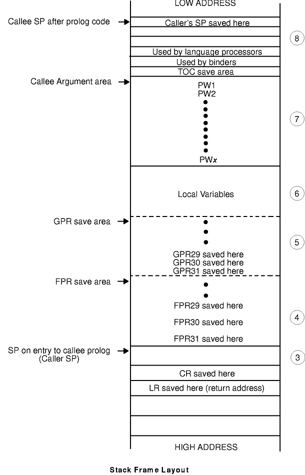
No predetermined code sequences representing function prologs and epilogs are dictated. However, certain operations must be performed under certain conditions. The Stack Frame Layout figure shows the stack frame layout.
A typical function's execution stack is:
The Prolog Actions and Epilog Actions tables show the conditions and actions required for prologs and epilogs.
| Prolog Actions | |
| If: | Then: |
| Any nonvolatile FPRs (FPR14:FPR31) are used | Save them in the FPR save area (area 4 in the previous figure). |
| Any nonvolatile GPRs (GPR13:GPR31) are used | Save them in the GPR save area (area 5 in the previous figure). |
| LR is used for a nonleaf procedure | Save the LR at offset eight from the caller function SP. |
| Any of the nonvolatile condition register (CR) fields are used. | Save the CR at offset four from the caller function SP. |
| A new stack frame is required | Get a stack frame and decrement the SP by the size of the frame padded (if necessary) to a multiple of 16 to acquire a new SP and save caller's SP at offset 0 from the new SP. |
Note: A leaf function that does not require stack space for local variables and temporaries can save its caller registers at a negative offset from the caller SP without actually acquiring a stack frame.
| Epilog Actions | |
| If: | Then: |
| Any nonvolatile FPRs were saved | Restore the FPRs that were used. |
| Any nonvolatile GPRs were saved | Restore the GPRs that were saved. |
| The LR was altered because a nonleaf procedure was invoked | Restore LR. |
| The CR was altered | Restore CR. |
| A new stack was acquired | Restore the old SP to the value it had on entry (the caller's SP). Return to caller. |
While the PowerPC architecture provides both load and store multiple instructions for GPRs, it discourages their use because their implementation on some machines may not be optimal. In fact, use of the load and store multiple instructions on some future implementations may be significantly slower than the equivalent series of single word loads or stores. However, saving many FPRs or GPRs with single load or store instructions in a function prolog or epilog leads to increased code size. For this reason, the system environment must provide routines that can be called from a function prolog and epilog that will do the saving and restoring of the FPRs and GPRs. The interface to these routines, their source code, and some prolog and epilog code sequences are provided .
As shown in the stack frame layout, the GPR save area is not at a fixed position from either the caller SP or the callee SP. The FPR save area starts at a fixed position, directly above the SP (lower address) on entry to that callee, but the position of the GPR save area depends on the number of FPRs saved. Thus, it is difficult to write a general-purpose GPR-saving function that uses fixed displacements from SP.
If the routine needs to save both GPRs and FPRs, use GPR12 as the pointer for saving and restoring GPRs. (GPR12 is a volatile register, but does not contain input parameters.) This results in the definition of multiple-register save and restore routines, each of which saves or restores m FPRs and n GPRs. This is achieved by executing a bla (Branch and Link Absolute) instruction to specially provided routines containing multiple entry points (one for each register number), starting from the lowest nonvolatile register.
Notes:
- There are no entry points for saving and restoring GPR and FPR numbers greater than 29. It is more efficient to save a small number of registers in the prolog than it is to call the save and restore functions.
- If the LR is not saved or restored in the following code segments, the language processor must perform the saving and restoring as appropriate.
Language processors must use a proprietary method to conserve the values of nonvolatile registers across a function call.
Three sets of save and restore routines must be made available by the system environment. These routines are:
For a function that saves and restores n GPRs and no FPRs, the saving can be done using individual store and load instructions or by calling system-provided routines as shown in the following example:
Note: The number of registers being saved is n. Sequences such as <32-n> in the following examples indicate the first register number to be saved and restored. All registers from <32-n> to 31, inclusive, are saved and restored.
#Following are the prolog/epilog of a function that saves n GPRS #(n>2):
mflr    r0                       #move LR into GPR0
bla     _savegpr0_<32-n>         #branch and link to save GPRs
stwu    r1,<-frame_size>(r1)     #update SP and save caller's SP
...                              #frame_size is the size of the
                                 #stack frame to be required
<save CR if necessary>
...
...                              #body of function
...
<reload save CR if necessary>
...
<reload caller's SP into R!>     #see note below
ba      _restgpr0_<32-n>         #restore GPRs and return
Note: The restoring of the calling function SP can be done by either adding the frame_size value to the current SP whenever frame_size is known, or by reloading it from offset 0 from the current SP. The first approach is more efficient, but not possible for functions that use the alloca subroutine to dynamically allocate stack space.
The following example shows a GPR save routine when FPRs are not saved:
_savegpr0_13    stw     r13,-76(r1)              #save r13
_savegpr0_14    stw     r14,-72(r1)              #save r14
_savegpr0_15    stw     r15,-68(r1)              #save r15
_savegpr0_16    stw     r16,-64(r1)              #save r16
_savegpr0_17    stw     r17,-60(r1)              #save r17
_savegpr0_18    stw     r18,-56(r1)              #save r18
_savegpr0_19    stw     r19,-52(r1)              #save r19
_savegpr0_20    stw     r20,-48(r1)              #save r20
_savegpr0_21    stw     r21,-44(r1)              #save r21
_savegpr0_22    stw     r22,-40(r1)              #save r22
_savegpr0_23    stw     r23,-36(r1)              #save r23
_savegpr0_24    stw     r24,-32(r1)              #save r24
_savegpr0_25    stw     r25,-28(r1)              #save r25
_savegpr0_26    stw     r26,-24(r1)              #save r26
_savegpr0_27    stw     r27,-20(r1)              #save r27
_savegpr0_28    stw     r28,-16(r1)              #save r28
_savegpr0_29    stw     r29,-12(r1)              #save r29
                stw     r30,-8(r1)               #save r30
                stw     r31,-4(r1)               #save r31
                stw     r0 , 8(r1)               #save LR in
                                                 #caller's frame
                blr                              #return
Note: This save routine must not be called when GPR30 or GPR31, or both, are the only registers beings saved. In these cases, the saving and restoring must be done inline.
The following example shows a GPR restore routine when FPRs are not saved:
_restgpr0_13    lwz     r13,-76(r1)              #restore r13
_restgpr0_14    lwz     r14,-72(r1)              #restore r14
_restgpr0_15    lwz     r15,-68(r1)              #restore r15
_restgpr0_16    lwz     r16,-64(r1)              #restore r16
_restgpr0_17    lwz     r17,-60(r1)              #restore r17
_restgpr0_18    lwz     r18,-56(r1)              #restore r18
_restgpr0_19    lwz     r19,-52(r1)              #restore r19
_restgpr0_20    lwz     r20,-48(r1)              #restore r20
_restgpr0_21    lwz     r21,-44(r1)              #restore r21
_restgpr0_22    lwz     r22,-40(r1)              #restore r22
_restgpr0_23    lwz     r23,-36(r1)              #restore r23
_restgpr0_24    lwz     r24,-32(r1)              #restore r24
_restgpr0_25    lwz     r25,-28(r1)              #restore r25
_restgpr0_26    lwz     r26,-24(r1)              #restore r26
_restgpr0_27    lwz     r27,-20(r1)              #restore r27
_restgpr0_28    lwz     r28,-16(r1)              #restore r28
_restgpr0_29    lwz     r0,8(r1)                 #get return
                                                 #address from
                                                 #frame
                lwz     r29,-12(r1)              #restore r29
                mtlr    r0                       #move return
                                                 #address to LR
                lwz     r30,-8(r1)               #restore r30
                lwz     r31,-4(r1)               #restore r31
                blr                              #return
Note: This restore routine must not be called when GPR30 or GPR31, or both, are the only registers beings saved. In these cases, the saving and restoring must be done inline.
For a function that saves and restores n GPRs and m FPRs (n>2 and m>2), the saving can be done using individual store and load instructions or by calling system-provided routines as shown in the following example:
#The following example shows the prolog/epilog of a function #which save n GPRs and m FPRs:
mflr    r0                       #move LR into GPR 0
subi    r12,r1,8*m               #compute GPR save pointer
bla     _savegpr1_<32-n>         #branch and link to save GPRs
bla     _savefpr_<32-m>
stwu    r1,<-frame_size>(r1)     #update SP and save caller's SP
...
<save CR if necessary>
...
...                              #body of function
...
<reload save CR if necessary>
...
<reload caller's SP into r1>     #see note below on
subi    r12,r1,8*m               #compute CPR restore pointer
bla     _restgpr1_<32-n>         #restore GPRs
ba      _restfpr_<32-m>          #restore FPRs and return
Note: The calling function SP can be restored by either adding the frame_size value to the current SP whenever the frame_size is known or by reloading it from offset 0 from the current SP. The first approach is more efficient, but not possible for functions that use the alloca subroutine to dynamically allocate stack space.
The following example shows a GPR save routine when FPRs are saved:
_savegpr1_13    stw     r13,-76(r12)             #save r13
_savegpr1_14    stw     r14,-72(r12)             #save r14
_savegpr1_15    stw     r15,-68(r12)             #save r15
_savegpr1_16    stw     r16,-64(r12)             #save r16
_savegpr1_17    stw     r17,-60(r12)             #save r17
_savegpr1_18    stw     r18,-56(r12)             #save r18
_savegpr1_19    stw     r19,-52(r12)             #save r19
_savegpr1_20    stw     r20,-48(r12)             #save r20
_savegpr1_21    stw     r21,-44(r12)             #save r21
_savegpr1_22    stw     r22,-40(r12)             #save r22
_savegpr1_23    stw     r23,-36(r12)             #save r23
_savegpr1_24    stw     r24,-32(r12)             #save r24
_savegpr1_25    stw     r25,-28(r12)             #save r25
_savegpr1_26    stw     r26,-24(r12)             #save r26
_savegpr1_27    stw     r27,-20(r12)             #save r27
_savegpr1_28    stw     r28,-16(r12)             #save r28
_savegpr1_29    stw     r29,-12(r12)             #save r29
                stw     r30,-8(r12)              #save r30
                stw     r31,-4(r12)              #save r31
                blr                              #return
The following example shows an FPR save routine:
_savefpr_14    stfd     f14,-144(r1)             #save f14
_savefpr_15    stfd     f15,-136(r1)             #save f15
_savefpr_16    stfd     f16,-128(r1)             #save f16
_savefpr_17    stfd     f17,-120(r1)             #save f17
_savefpr_18    stfd     f18,-112(r1)             #save f18
_savefpr_19    stfd     f19,-104(r1)             #save f19
_savefpr_20    stfd     f20,-96(r1)              #save f20
_savefpr_21    stfd     f21,-88(r1)              #save f21
_savefpr_22    stfd     f22,-80(r1)              #save f22
_savefpr_23    stfd     f23,-72(r1)              #save f23
_savefpr_24    stfd     f24,-64(r1)              #save f24
_savefpr_25    stfd     f25,-56(r1)              #save f25
_savefpr_26    stfd     f26,-48(r1)              #save f26
_savefpr_27    stfd     f27,-40(r1)              #save f27
_savefpr_28    stfd     f28,-32(r1)              #save f28
_savefpr_29    stfd     f29,-24(r1)              #save f29
               stfd     f30,-16(r1)              #save f30
               stfd     f31,-8(r1)               #save f31
               stw      r0 , 8(r1)               #save LR in
                                                 #caller's frame
               blr                               #return
The following example shows a GPR restore routine when FPRs are saved:
_restgpr1_13    lwz     r13,-76(r12)             #restore r13
_restgpr1_14    lwz     r14,-72(r12)             #restore r14
_restgpr1_15    lwz     r15,-68(r12)             #restore r15
_restgpr1_16    lwz     r16,-64(r12)             #restore r16
_restgpr1_17    lwz     r17,-60(r12)             #restore r17
_restgpr1_18    lwz     r18,-56(r12)             #restore r18
_restgpr1_19    lwz     r19,-52(r12)             #restore r19
_restgpr1_20    lwz     r20,-48(r12)             #restore r20
_restgpr1_21    lwz     r21,-44(r12)             #restore r21
_restgpr1_22    lwz     r22,-40(r12)             #restore r22
_restgpr1_23    lwz     r23,-36(r12)             #restore r23
_restgpr1_24    lwz     r24,-32(r12)             #restore r24
_restgpr1_25    lwz     r25,-28(r12)             #restore r25
_restgpr1_26    lwz     r26,-24(r12)             #restore r26
_restgpr1_27    lwz     r27,-20(r12)             #restore r27
_restgpr1_28    lwz     r28,-16(r12)             #restore r28
_restgpr1_29    lwz     r29,-12(r12)             #restore r29
                lwz     r30,-8(r12)              #restore r30
                lwz     r31,-4(r12)              #restore r31
                blr                              #return
The following example shows an FPR restore routine:
_restfpr_14    lfd     r14,-144(r1)              #restore r14
_restfpr_15    lfd     r15,-136(r1)              #restore r15
_restfpr_16    lfd     r16,-128(r1)              #restore r16
_restfpr_17    lfd     r17,-120(r1)              #restore r17
_restfpr_18    lfd     r18,-112(r1)              #restore r18
_restfpr_19    lfd     r19,-104(r1)              #restore r19
_restfpr_20    lfd     r20,-96(r1)               #restore r20
_restfpr_21    lfd     r21,-88(r1)               #restore r21
_restfpr_22    lfd     r22,-80(r1)               #restore r22
_restfpr_23    lfd     r23,-72(r1)               #restore r23
_restfpr_24    lfd     r24,-64(r1)               #restore r24
_restfpr_25    lfd     r25,-56(r1)               #restore r25
_restfpr_26    lfd     r26,-48(r1)               #restore r26
_restfpr_27    lfd     r27,-40(r1)               #restore r27
_restfpr_28    lfd     r28,-32(r1)               #restore r28
_restfpr_29    lwz     r0,8(r1)                  #get return
                                                 #address from
                                                 #frame
               lfd     r29,-24(r1)               #restore r29
               mtlr    r0                        #move return
                                                 #address to LR
               lfd     r30,-16(r1)               #restore r30
               lfd     r31,-8(r1)                #restore r31
               blr                               #return
For a function that saves and restores m FPRs (m>2), the saving can be done using individual store and load instructions or by calling system-provided routines as shown in the following example:
#The following example shows the prolog/epilog of a function #which saves m FPRs and no GPRs:
mflr    r0                       #move LR into GPR 0
bla     _savefpr_<32-m>
stwu    r1,<-frame_size>(r1)     #update SP and save caller's SP
...
<save CR if necessary>
...
...                              #body of function
...
<reload save CR if necessary>
...
<reload caller's SP into r1>     #see note below
ba      _restfpr_<32-m>          #restore FPRs and return
Notes:
- There are no entry points for saving and restoring GPR and FPR numbers higher than 29. It is more efficient to save a small number of registers in the prolog than to call the save and restore functions.
- The restoring of the calling function SP can be done by either adding the frame_size value to the current SP whenever frame_size is known, or by reloading it from offset 0 from the current SP. The first approach is more efficient, but not possible for functions that use the alloca subroutine to dynamically allocate stack space.
The PowerPC stwu (Store Word with Update) instruction is used for computing the new SP and saving the back chain. This instruction has a signed 16-bit displacement field that can represent a maximum signed value of 32,768. A stack frame size greater than 32K bytes requires two instructions to update the SP, and the update must be done atomically.
The two assembly code examples illustrate how to update the SP in a prolog.
To compute a new SP and save the old SP for stack frames larger than or equal to 32K bytes:
addis   r12, r0, (<-frame_size> > 16) & 0XFFFF
                        # set r12 to left half of frame size
ori     r12, r12 (-frame_size> & 0XFFFF
                        # Add right halfword of frame size
stwux   r1, r1, r12     # save old SP and compute new SP
To compute a new SP and save the old SP for stack frames smaller than 32K bytes:
stwu r1, <-frame_size>(r1) #update SP and save caller's SP
When an assembler language program calls another program, the caller should not use the names of the called program's commands, functions, or procedures as global assembler language symbols. To avoid confusion, follow the naming conventions for the language of the called program when you create symbol names. For example, if you are calling a C language program, be certain you use the naming conventions for that language.
A called routine has two symbols associated with it: a function descriptor (Name) and an entry point (.Name). When a call is made to a routine, the compiler branches to the name point directly.
Except for when loading parameters into the proper registers, calls to functions are expanded by compilers to include an NOP instruction after each branch and link instruction. This extra instruction is modified by the linkage editor to restore the contents of the TOC register (register 2) on return from an out-of-module call.
The instruction sequence produced by compilers is:
bl .foo            #Branch to foo
cror 31,31,31     #Special NOP 0x4ffffb82
Note: Some compilers produce a cror 15,15,15 (0x4def7b82) instruction. To avoid having to restore condition register 15 after a call, the linkage editor transforms cror 15,15,15 into cror 31,31,31. Condition register bit 31 is not preserved across a call and does not have to be restored.
The linkage editor will do one of two things when it sees the bl instruction (in the previous instruction sequence, on a call to the foo function):
bl .glink_of_foo  #Branch to global linkage routine for foo
l 2,20(1)         #Restore TOC register instruction 0x80410014
The bl .glink_of_foo instruction sequence is changed to:
bl .foo         #Branch to foo
cror 31,31,31   #Special NOP instruction 0x4ffffb82
Note: For any export, the linkage editor inserts the procedure's descriptor into the module.
Prologs and epilogs are used in the called routines. On entry to a routine, the following steps should be performed:
Note: If a stack overflow occurs, it will be known immediately when the store of the back chain is completed.
On exit from a procedure, perform the following step:
Every assembly (compiled) program needs traceback information for the debugger to examine if the program traps or crashes during execution. This information is in a traceback table at the end of the last machine instruction in the program and before the program's constant data.
The traceback table starts with a full word of zeros, X'00000000', which is not a valid system instruction. The zeros are followed by 2 words (64 bits) of mandatory information and several words of optional information, as defined in the /usr/include/sys/debug.h file. Using this traceback information, the debugger can unwind the CALL chain and search forward from the point where the failure occurred until it reaches the end of the program (the word of zeros).
In general, the traceback information includes the name of the source language and information about registers used by the program, such as which general-purpose and floating-point registers were saved.
The following is an example of assembler code called by a C routine:
#      Call this assembly routine from C routine:
#       callfile.c:
#       main()
#       {
#       examlinkage();
#       }
#       Compile as follows:
#       cc -o callfile callfile.c examlinkage.s
#
#################################################################
#       On entry to a procedure(callee), all or some of the
#       following steps should be done:
#       1.  Save the link register at offset 8 from the
#           stack pointer for non-leaf procedures.
#       2.  If any of the CR bits 8-19(CR2,CR3,CR4) is used
#           then save the CR at displacement 4 of the current
#            stack pointer.
#       3.  Save all non-volatile FPRs used by this routine.
#           If more that three non-volatile FPR are saved,
#            a call to ._savefn can be used to
#           save them (n is the number of the first FPR to be
#            saved).
#       4.  Save all non-volatile GPRs used by this routine
#           in the caller's GPR SAVE area (negative displacement
#           from the current stack pointer r1).
#       5.  Store back chain and decrement stack pointer by the
#           size of the stack frame.
#
#       On exit from a procedure (callee), all or some of the
#       following steps should be done:
#       1.  Restore all GPRs saved.
#       2.  Restore stack pointer to value it had on entry.
#       3.  Restore Link Register if this is a non-leaf
#           procedure.
#       4.  Restore bits 20-31 of the CR is it was saved.
#       5.  Restore all FPRs saved.  If any FPRs were saved then
#           a call to ._savefn can be used to restore them
#           (n is the first FPR to be restored).
#       6.  Return to caller.
#################################################################
#       The following routine calls printf() to print a string.
#       The routine performs entry steps 1-5 and exit steps 1-6.
#       The prolog/epilog code is for small stack frame size.
#       DSA + 8 < 32k
#################################################################
        .file   "examlinkage.s"
#Static data entry in T(able)O(f)C(ontents)
        .toc
T.examlinkage.c:        .tc     examlinkage.c[tc],examlinkage.c[rw]
        .globl  examlinkage[ds]
#examlinkage[ds] contains definitions needed for
#runtime linkage of function examlinkage
        .csect  examlinkage[ds]
        .long   .examlinkage[PR]
        .long   TOC[tc0]
        .long   0
#Function entry in T(able)O(f)C(ontents)
        .toc
T.examlinkage:  .tc     .examlinkage[tc],examlinkage[ds]
#Main routine
        .globl  .examlinkage[PR]
        .csect  .examlinkage[PR]
#       Set current routine stack variables
#       These values are specific to the current routine and
#       can vary from routine to routine
        .set    argarea,     32
        .set    linkarea,    24
       .set    locstckarea,   0
        .set    nfprs,       18
        .set    ngprs,       19
        .set    szdsa,
8*nfprs+4*ngprs+linkarea+argarea+locstckarea
#PROLOG:  Called Routines Responsibilities
        #    Get link reg.
        mflr    0
        #    Get CR if current routine alters it.
        mfcr    12
        #    Save FPRs 14-31.
        bl      ._savef14
        cror 31, 31, 31
        #    Save GPRs 13-31.
        stm     13, -8*nfprs-4*ngprs(1)
        #    Save LR if non-leaf routine.
        st      0, 8(1)
        #    Save CR if current routine alters it.
        st      12, 4(1)
        #    Decrement stack ptr and save back chain.
        stu     1, -szdsa(1)
################################
#load static data address
#################################
        l       14,T.examlinkage.c(2)
        #  Load string address which is an argument to printf.
        cal 3, printing(14)
        #  Call to printf routine
        bl      .printf[PR]
        cror 31, 31, 31
#EPILOG:  Return Sequence
        #    Restore stack ptr
        ai      1, 1, szdsa
        #    Restore GPRs 13-31.
        lm      13, -8*nfprs-4*ngprs(1)
        #    Restore FPRs 14-31.
        bl      ._restf14
        cror 31, 31, 31
        #    Get saved LR.
        l       0, 8(1)
        #    Get saved CR if this routine saved it.
        l       12, 4(1)
        #    Move return address to link register.
        mtlr    0
        #    Restore CR2, CR3, & CR4 of the CR.
        mtcrf   0x38,12
        #    Return to address held in Link Register.
        brl
.tbtag 0x0,0xc,0x0,0x0,0x0,0x0,0x0,0x0
          #       External variables
        .extern ._savef14
        .extern ._restf14
        .extern .printf[PR]
#################################
#       Data
#################################
        .csect  examlinkage.c[rw]
        .align  2
printing:       .byte  'E,'x,'a,'m,'p,'l,'e,' ,'f,'o,'r,'
                .byte   'P,'R,'I,'N,'T,'I,'N,'G
        .byte   0xa,0x0
All of the fixed-point divide instructions, and some of the multiply instructions, are different for POWER and PowerPC. To allow programs to run on systems based on either architecture, a set of special routines is provided by the operating system. These are called milicode routines and contain machine-dependent and performance-critical functions. Milicode routines are located at fixed addresses in the kernel segment. These routines can be reached by a bla instruction. All milicode routines use the link register.
Notes:
- No unnecessary registers are destroyed. Refer to the definition of each milicode routine for register usage information.
- Milicode routines do not alter any floating-point register, count register, or general-purpose registers (GPRs) 10-12. The link register can be saved in a GPR (for example, GPR 10) if the call appears in a leaf procedure that does not use nonvolatile GPRs.
- Milicode routines do not make use of a TOC.
The following milicode routines are available:
The following example uses the mulh milicode routine in an assembler program:
li R3, -900
li R4, 50000
bla .__mulh
...
.extern .__mulh
Assembling and Linking a Program.
Understanding Assembler Passes.
Interpreting an Assembler Listing.
Interpreting a Symbol Cross-Reference.
Understanding and Programming the TOC.
The b (Branch) instruction, cror (Condition Register OR) instruction.